Project Overview:

The purpose of this project was to display the day, month, and year of my birthday using a seven segment display. To do so I set up a truth table for all the numbers that make up my birthday. I K mapped each individual output so that i could create the most simplified expression for my circuit. Lucky the numbers in my birthday were simply so I didn't need to use any Boolean algebra to simplify it any further. When we created the circuits the only component (Other that the gates and segment display)that was necessary was a resistor, I chose to use one that was 220 Ohm. This report will explain the process of creating a real life circuit starting with only a truth table.
Truth Table:
The purpose of the truth table was to give me a starting place for the project. It showed me what switches needed to be on and off for certain numbers to appear, and it also gave me an idea of what segments needed to appear for certain numbers.
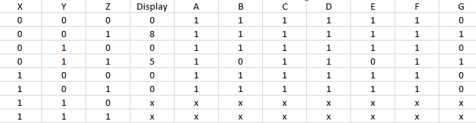
The display column shows the date of my birth in order from month to day to year. Therefore 08 is the month, 05 is the day, and 00 is the year. We have the columns A through G because they represent each segment of the display, so it shows you what segments need to be on so that the corresponding number will be shown. The letter X means that it doesn't matter whether the number is a one or a zero for columns A through G,because we don't care what the corresponding last two numbers are. We are only worried about the month, day, and last two digits of the year. Therefore X can be either a 1 or a 0.
K mapping and Simplified Logic Expressions:
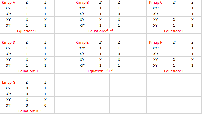
K mapping works by taking a section of the truth table and creating a smaller table to then create an expression for that segment. For example you would take the numbers in column A through G for each display number and listen them going from left to right and top to bottom. The numbers would be in the order of 1,2,3,4,7,8,5,6. On the K maps, the farthest left column and the top row always contain the input variables for the displays. I must have every different possible combinations of the inputs and I can only change one sign at a time. That is why it goes from both X and Y being X'Y' to X'Y to XY to XY'. Same thing for the Z. From there I have to create the expressions so I go ahead and group all the ones in the biggest groups possible. From there i look up and left to see what variables they have in common between each 1. Finally i combined the variables and add them to the next K map. This method is a SOP because we are multiplying within the k maps and adding it to the next one. The reason for using K mapping is because it takes significantly less time than Boolean algebra and there is less of a chance of me messing up the simplification of the expressions. I have 7 expressions because I need and expression for each segment display.
Multi-sim Implementation:
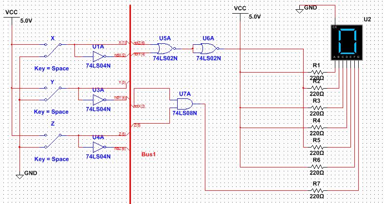
Pictured above is the seven segment Birthday Display Circuit. Yes this is BUS form because both the inputs and circuits are brought together by the BUS line. For this circuit you need at least one AND gate, one NOR gate, and 3 inverters. The number of chips required would be at least three. That is because you need a chip for all the inverters, a chip for the AND gate, and a chip for the NOR gates. I had no intentional purpose for using the NOR gates for segments B and E. It just happened to be that most of my segments were 1's s i only had 3 actually circuits to build. So i chose segment B and E because there wasn't much to chose from and because both segments had the same set up. We use NAND and NOR gates because they are universal gates, if you have limited supplies you can use either of these gates to complete an inversion, an and, or an or task. They can do it all. If I were to use a normal OR gate I would end up still using 3 chips. Therefore it doesn't make it any more or any less efficient from using the standard gates. This is important to check because f you are building these gates for a business, its good to know how to accomplish the same task with the least amount of material so that you can save on time and money. A seven segment display works by having an input at each segment and to display a certain letter or number you have to light the segments up in a certain order to display that output. for example if you wanted to display the number 8 you would have to turn on every segment so that every part of the 8 was showing. The difference between cathode and anode is that the cathode display is connected to ground while the anode display is connected to power. SO what ever the display is connected to, you must bring in the opposite power for the segment to light up. Therefore cathodes must have inputs of power and anodes need inputs of ground. We are using a common cathode because it i much easier to think of a 1 being powered than it s to thin of a 0 when you are creating the inputs for each of the segments. It is easier for the users to work with because usually people associate 0 being no power. Finally the purpose of the resistor right before each segment is to control the amount of energy coming o the display this is just to ensure you don't blow out any lights during the process.
Bills of material:

Up above shows the bill of materials, the left column shows each type of component and the right column shows the quantity of each of those components.
Bread Boarding:

|

|

|
The picture to the left shows the bread board and all the pieces before construction, in the middle shows me wiring the components together, and on the right shows me admiring all the work i had done. for my second time bread boarding I had improved a lot for the first time. This time around I knew hoe to place the wires in the correct positions and how to get them to combined with one another. The only problem that occurred was that I had placed the wires in the wrong slots for the NOR gate because NOR chips have their inputs and outputs opposite of other normal chips. I trouble shot a couple of times before looking at the diagram and realizing my mistake. Once I rewired it correctly I had no problem getting the right display from it. My gates weren't laid out in a certain order i just made sure when i wired, i wired in an organized way and color coded each segment so that I wouldn't get lost looking back at it.
Conclusion:
I learned a great deal from this project. First off I learned that the inputs and output slots of NOR chips are opposite of the other normal chips, therefore I had to be careful when bread boarding. I also learned how each segment of the seven segment display gets lit up, each segment has a different circuit connected to it. The only thing that I would do differently a second time is do my truth table directly on excel because it looks a lot neater and is easier to read. I lost a couple of minutes when I redid my truth table on excel. Honestly I do not have any more questions about this subject or topic, I am really proud of how far I've come and how much I've been able to understand everything. It feels nice to be ahead of the game and be able to help someone in that class that is struggling, K mapping is extremely useful and I definitely recommend it. Instead of using algebra to solve expressions, I can simply make a chart and connect all the ones in groups and have my expression done. It is very user friendly, time efficient, and easy to keep track of. The only compliant would be the shortage of wire cutters. Too many people with two wire cutters did not help any of our situations. However as always I had a enjoyable time completing this project.
