Project Overview:
The intention of this project was to build a circuit that counted 0-80, and once it hits 80 its needs to pause. To do so I built two separate circuits one that counted 0-8 ( tens place), and one that counted 0-9(ones place). The circuit also included a reset switch that reset the count from 0 at anytime. This count was displayed by using two common cathode displays.

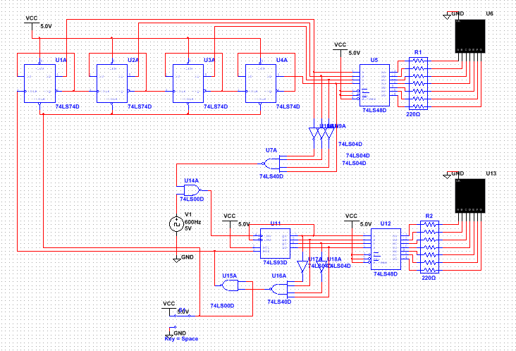
Multisim Circuit:
PLD Circuit:
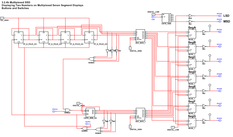
PLD mode uses components such as DIO's as inputs and outputs on the other hand design mode uses switches as inputs and LED lights as outputs. In this assignment the reset switch and clock were the inputs while the seven segments of the display were the outputs. The difference between input and output connectors is the direction of where the wires goes. For inputs the wire goes to the right while outputs have them going to the left. To upload the circuit you go to transfer, export to pld, and send it to the cmods6 that is connected to the circuit board.
Bill of materials:

Conclusion:
The main difference between SSI and MSI is that MSI allows you to use more gates for every IC chip. Therefore working with MSI is much simpler and efficient.
The only limitations for the MSI circuit we built was that it can only count up and it has to begin with 0.
The ripple Effect is a phrase to show that the circuit works within a series and every flip flop will act based on the previous flip flops signal. They all work as if they were in a chain.
My circuit begins with the PIO14 as my input which runs into the 74ls93 gate which will cunt the single digit place in my circuit. Using a NAND gate, once the singe digit reaches 9 it will trigger the tens place to increase by one. The tens place uses a series of D-Flip-Flops that will make the the tens place count from 0-8. Then using a AND gate, once the tens places reaches 8 the circuit will automatically stop until the reset switch is activated.
Other than how the wiring was set up, my classmates didn't have very different circuits. We all had the same output set up as it were given to us. Also we all built two circuits one that counted 0-9 and one that counted 0-8. All other features were very similar except where we placed our components and the wiring.
