
Project Overview:
The purpose of creating this circuit design, is to ensure a way that all voter are accounted for. So that no individual is double counted or not counted at all. Using only two-input gates, we are representing the votes of each office holder. In case of a tie, it is up to the presidents vote to see if it passes or not. If the president in on with any other person the light will be lit. Another case is if the majority of the four pass it. So if any three pass it, the light will be lit.
Problem Conception (Truth Table and Simplified Expression):
Below is the truth table for the simplified circuit, it represents all the circumstances needed for the decision to pass. It shows that in order for the decision to pass the majority of the inputs, so 3 out of the 4, must pass the bill. In case of a tie between members, the presidents vote will decide if the decision will pass. Due to the fact that there is 4 different inputs, there can be a total of 16 different combinations. You can figure out how many combinations there are by using the formula 2 to the N power. N is the number of inputs you have, therefore 2 to the 4th power gives you 16 different combinations. It is very important to have a truth table because you ca create a expression from it and from the expression you can create a circuit. With the circuit being built then, so can double check your work to see if the truth table matches up with the circuit.

Shown below is the un-simplified version of the table truth shown above. It takes each one of the circumstances where the decision is passed and adds them all together. They way I arrived at each minterm was that i went down the table from top to bottom and checked off all the places where the decision was a 1. The result was there was 8 of those places, therefore I would need 8 minterms. Starting with the fist one i saw what each variable was, whether it was on or off. If on, i would just write down its letter, if off i would write its letter with a dash above. When i was done multiplying the first set of circumstances i moved to the next one, I did this until all 8 were done. In the end I added them all together. I chose SOP because it was easier to multiply each row and then add it to the next one needed.

Un-Simplified Circuit:
|
The circuit shown to the right was completed using the un-simplified expression for the problem. It represents all 8 minterms using a total of 16 AND gates, 15 OR gates, and 4 inverts. Since these were only two input gates, each minterm had to be cut into two pieces. This means I had to multiply the first two terms then multiply the second two terms, then multiply the products together. This step had to be repeated a total of eight times. Getting the wires to where they needed to be was accomplished by branching off existing wires, that is why the circuit looks bundled up. Thus making the circuit to be bus form, because each of the components must link together before going on to the next process of the circuit. Next, since it was a sum of products circuit I had to add all the products together. That's where the or gates played a role. Once again these gates were had a max of two inputs, so i had to add two by two several times. Once they were all added together i could place my LED. The LED will light up if you follow any of those 8 minterms, for example the first one, if you turn off p and turn on all the rest the LED will light up. Same goes for the other 7. However for the circuit to be complete I had to connect each variable to the power source and to the ground.
|

|
Boolean Algebra Simplification:
In order to make the circuit much more cost efficient, and a lot less complicated. I used Boolean algebra to simplify the expression in order to use a lot less gates and wires.

Simplified Circuit:
|
To the right is the simplified circuit of the problem. It requires only 7 AND gates, 2 OR gates, and 1 inverter. So this uses a total of 10 gates which is 25 less than the un-simplified circuit, which is a huge difference. As before the circuit is still in bus from because all the variables and components interconnect with each other before moving onto the next stage process. The resistor at the end of the circuit before the LED was placed there to limit the amount of energy flow going to the LED. Making sure the LED wouldn't burn out or break.
Yes this circuit is much more simplified and contains less gates. To find out is really easy, you can tell by just counting the number of gates in each one and youll find out this circuit has 25 less gates. So when building in the real world it would be better off to use the simplified version for many reasons. One reason is that it would save the builder a lot of money. Instead of buying 35 gates and all the wiring needed to connect those gates for the fist circuit, you can just buy 10 gates for the simplified version. Also it saves a lot of time when building and the chance of a mistake happening when construction is taking place majorly decreases. This is because there is less components to keep track off. That's why simplified circuits are better to work with. |

|
Bill of materials:
Below is the price chart for the simplified circuit. The first column simply tells you what component is being looked at. The second column is representing how many of the gates you're looking at that you have. The third column is the unit cost per gate. Since I don't know what the price is actually i used the variable x to represent cost. The last column shows that you multiply the quantity by price to give you the total price for each gate. Then to find the total amount for the entire circuit you add up all the individual prices you just found.

Bread-Boarding:
|
|
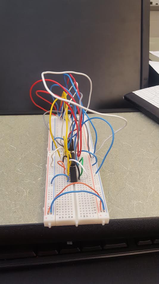
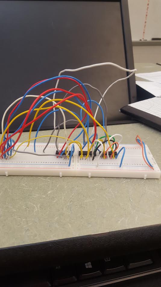
Above are three pictures of the same circuit. This is a hand made version of the simplified circuit on multism. The only component missing is the green board which holds the variables and led lights. However you can still tell the roles of the wires and chips. All the wires originate from either P, V, S, or T. From there based on the simplified expression, each wire is sent to the and gate to be multiplied and then added to the or gate to be added. Once all 4 multiplications have been added to the or gate, I added the two products together and then added those sums together into a final output. From there i sent to wire to the LED to check if all my wires were set up correctly. When I first tried to see if my board was working I found out that it was set up incorrectly, I went back to my work area and re looked at the gate diagrams. I concluded that i had accidentally placed my inputs and output one spot to the left, once I fixed that my board was running perfectly.
Conclusion:
This project ended up being very enlightening. My proudest moment was when I grasped the idea of how the bread board worked and how it needed to be set up. Within that I learned that each gate has certain ports for power, ground, inputs, and outputs. That is very helpful to know when you are connecting wires. Once a classmate showed me how to set up the first two wires, i flew by it on my own, everything started to click for me. The most trouble I had was creating the un-simplified circuit on the computer. This was because i kept losing my place in the wires and they got too bundled up for me to tell them apart. I liked how we had a lot of class time to work on this project because i truly got to sit down and figure out what i was doing. The way i saw this process was, you start with a problem, you create a truth table for it. Then you create an expression for that truth table and then simplify it. From their you can build a simplified circuit on the computer and then do it in real life. Boolean algebra played a major major role. It was very important because it simplified to circuit to the point where it took off 25 unneeded gates. Which means you save time, money, and energy to build the circuit. It is much easier to read, and there a lesser chance of messing the building process up. Boolean algebra is the way to go. Overall I enjoyed participating in the project!
